News
Contact Us
Service telephone
+86 0391-8299688
Email:LeruiTools@hotmail.com
Address:No. 99, East Wengong Road, High-tech Industrial Development Zone, Xiguo Town, Mengzhou City, Jiaozuo City, Henan Province, China
Sales Manager
+86 18303902299(Mr. Liu)
Sales Engineer
+86 16663799288(Mr. Li)
Several methods of controlling chip breaking in turning, LERUI chip breaker tool can better break chips and improve processing efficiency
When continuous banded chips are generated during processing, it is not only easy to scratch the workpiece surface and damage the blade, but also threaten the safety of the operator in severe cases. Therefore, taking necessary technological measures to control chip type and chip breaking has always been a mechanical process Process issues of paramount importance in the industry.
Since chips are the product of the deformation of the chip layer, changing the cutting conditions is an effective way to change the type of chips and achieve chip breaking. The factors that affect the conditions of chip processing mainly include workpiece material, tool geometric angle and chip amount.
Generally, the chips need to meet the following basic conditions: the chips must not be wrapped around the tool, the workpiece and its adjacent tools and equipment; the chips must not splash to ensure the safety of the operator and the observer; during finishing, the chips must not scratch the workpiece The machined surface will affect the quality of the machined surface; ensure the predetermined durability of the tool, do not wear it prematurely and try to prevent it from being damaged; when the chips flow out, it will not hinder the injection of cutting fluid; the chips will not scratch the machine guide rail or other parts etc.
1. Classification of chip shape
Due to the different degree of plastic deformation, different kinds of chips may be generated, as shown in Figure 1. When processing plastic materials, mainly band-shaped chips, nodular chips or granular chips are formed, and when processing brittle materials, crushed chips are generally formed.
1. Ribbon chips: Ribbon chips are continuous chips with smooth bottom and fluffy back, as shown in Figure 1-1a. Such chips are prone to occur when a tool with a larger rake angle is used to machine plastic metal materials at higher cutting speeds. It is the product of insufficient deformation of the cutting layer. When strip-shaped chips are generated, the cutting process is smooth and the surface roughness of the workpiece is small, but the chips are not easy to break, which often causes winding, slaps the workpiece, and even affects the operation, so its chip breaking problem cannot be ignored.
2. Nodal chip: Nodal chip is a chip with a smooth bottom surface, obvious cracks on the back, and deep cracks, as shown in Figure 1-1b. Such chips are prone to occur when machining plastic materials at lower cutting speeds using a tool with a reduced rake angle. It is the product of the fully deformed chip layer, which has reached the degree of shearing. When nodular chips are generated, the chip work is not stable and the surface roughness of the workpiece is large.
3. Granular chips: Granular chips are uniform granular chips, as shown in Figure 1-1c. Such chips are prone to occur when plastic metal materials are machined at very low cutting speeds with small rake angle tools. It is the product of the fully deformed cutting layer, which reaches the degree of shear failure of the material, so that the chips are broken along the thickness. When granular chips are generated, the cutting work is not stable and the surface roughness of the workpiece is large.
4. Crushing chips: Crushing chips are irregular fine-grained chips, as shown in Figure 1-1d. When cutting brittle materials, the cutting layer suddenly cracks after elastic deformation, almost without plastic deformation stage. When chipping is formed, the cutting work is unstable, the blade is subjected to a large impact force, and the machined surface is rough and uneven.
As can be seen from the above, the types of chips vary with the workpiece material and cutting conditions. Therefore, in the process of processing, it is possible to judge whether the chip conditions are suitable by observing the chip shape, and also to change the chip shape by converting the cutting conditions to make it transform in a direction that is beneficial to production.
Second, the principle of chip breaking
In the process of metal cutting, whether the chip is easy to break is directly related to the deformation of the chip, so the research on the principle of chip breaking must start with the study of the law of chip deformation.
Due to the relatively large plastic deformation of the chips formed in the cutting process, its hardness will increase, while the plasticity and toughness will be significantly reduced. This phenomenon is called cold work hardening. After cold work hardening, the chip becomes hard and brittle, and is easily broken when subjected to alternating bending or impact loads. The greater the plastic deformation experienced by the chip, the more obvious the phenomenon of hard and brittle, and the easier it is to break. When cutting high-strength, high-plasticity, and high-toughness materials that are difficult to break, try to increase the deformation of the chip to reduce its plasticity and toughness, so as to achieve the purpose of chip breaking.
The deformation of the chip can be composed of two parts:
The first part is formed during the cutting process, which we call the basic deformation. The chip deformation measured during free cutting with a flat rake face turning tool is relatively close to the value of the basic deformation. The main factors affecting the basic deformation are the rake angle of the tool, the negative chamfer, and the cutting speed. The smaller the rake angle, the wider the negative chamfer, and the lower the cutting speed, the greater the deformation of the chip, the more conducive to chip breaking. Therefore, reducing the rake angle, widening the negative chamfer, and reducing the cutting speed can be used as measures to promote chip breaking.
The second part is the deformation of the chip during the flow and curling process, which we call the additional deformation. Because in most cases, only the basic deformation during the cutting process cannot break the chip, and an additional deformation must be added to achieve the purpose of hardening and breaking. The easiest way to force the chips to undergo additional deformation is to grind (or press) a shaped chipbreaker on the rake face, forcing the chips into the chipbreaker and then curling and deforming. After the chip undergoes additional recoil deformation, it is further hardened and embrittled, and when it hits the workpiece or flank, it is easily broken.
3. Chip breaking method
The root cause of chip breaking and continuation is the deformation and stress in the process of chip formation. When the chip is in an unstable deformation state or the chip stress reaches its strength limit, the chip will break. Usually, the chip is curled and then broken.
Reasonable selection of tool geometry angle, cutting amount, and grinding chip breaker are commonly used chip breaking methods.
1. Reduce the rake angle and increase the main declination angle: the rake angle and the main declination angle are the geometrical angles of the tool that have a greater impact on chip breaking. Reduce the rake angle, aggravate the deformation of the chip, and be easy to break the chip. Grinding the rake angle to a small size will increase the cutting force, which limits the increase in the cutting amount. In severe cases, the tool will be damaged, or even "boring". Generally, it is not simply used to reduce the rake angle to break chips. Increasing the main declination angle can increase the cutting thickness and is easy to break chips. For example, under the same conditions, a 90° tool is easier to break than a 45° tool. In addition, increasing the main deflection angle is beneficial to reduce vibration during processing. Therefore, increasing the entering angle is an effective chip breaking method.
2. Reducing the cutting speed and increasing the feed to change the cutting amount is another measure for chip breaking. When the cutting speed is increased, the underlying metal of the chip becomes soft and the deformation of the chip is insufficient, which is not conducive to chip breaking; when the cutting speed is reduced, it is easy to break the chip. Therefore, during turning, chip breaking can be achieved by reducing the spindle speed and cutting speed. Increasing the feed rate can increase the cutting thickness and is easy to break chips. This is a commonly used chip breaking method in machining, but it should be noted that as the feed rate increases, the surface roughness value of the workpiece will increase significantly.
3. Open chip breaker: chip breaker refers to the groove made on the rake face of the tool. The shape, width and bevel angle of the chip breaker are all factors that affect chip breaking.
1) Shape of chip breaker
Commonly used chip breakers include broken line, straight arc, and full arc, as shown in Figure 2.
When cutting carbon steel, alloy steel, tool steel, broken line, straight arc, and chip breaker can be used; when cutting high-plastic material workpieces, such as pure copper, stainless steel workpieces, etc., full arc chip breakers can be used groove.
2) The width of the chip breaker
The width of the chipbreaker has a great effect on chip breaking. Generally speaking, the smaller the groove width, the smaller the curling radius of the chip, the greater the bending stress on the chip, and the easier it is to break. Therefore, it is beneficial to use a smaller chipbreaker width for chip breaking. But the chipbreaker width must be considered in relation to the feed depth of cut ɑp.
If the width of the chip breaker and the feed rate are basically suitable, C-shaped chips can be formed. If the chip flute is too narrow, it is easy to cause chip blocking, which increases the load of the turning tool and even damages the cutting edge; if the chip flute is too wide and the cutting curl radius is too large, the cutting deformation is not enough, it is not easy to break, and often does not flow through The bottom of the groove forms a continuous band-shaped chip.
The width of the chip groove should also be appropriate to the cutting depth. Otherwise, when the groove is too narrow, the chips will appear to be wide and not easy to curl in the groove. When the groove is too wide, the chips appear to be narrow, the flow is free, the deformation is not sufficient, and it does not break.
In order to obtain a satisfactory chip breaking effect, the appropriate chip breaker width should be selected according to the specific processing conditions. For workpiece materials with lower hardness, the groove should be selected narrower, and conversely, the groove should be selected wider.
Coated PCBN Inserts
Coated Pcbn Inserts
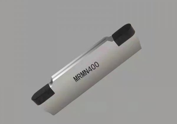
M Series Grooving PCBN Inserts
M Series Grooving PCBN Inserts
LBS series thoroughly brazed PCBN inserts
Thoroughly Brazed Pcbn Inserts
Honing Head
Honing Head